Rogers TMM® 3 Substrate Manufacturer
Rogers TMM® 3 Substrate Manufacturer,Rogers TMM® 3 Substrate is an advanced microwave material recognized for its exceptional performance in high-frequency applications. It features a low dielectric constant and low loss tangent, ensuring minimal signal loss and precise electrical characteristics crucial for RF and microwave circuits. Rogers TMM® 3 Substrate supports intricate circuit designs and high-speed signal transmission, vital for telecommunications, radar systems, and aerospace electronics. It offers reliable performance in challenging environments where signal integrity and thermal stability are essential. Widely utilized across industries, Rogers TMM® 3 Substrate provides robust solutions for applications demanding high reliability and superior electrical performance in demanding high-frequency electronic applications.
What is Rogers TMM® 3 Substrate?
Rogers TMM® 3 substrate is a high-frequency laminate designed for demanding RF (Radio Frequency) and microwave applications. It offers excellent electrical properties and mechanical stability, making it suitable for use in antennas, radar systems, and high-speed digital circuits where signal integrity and reliability are critical.
Key features of Rogers TMM® 3 include low dielectric constant (εr) and low loss tangent (tan δ), which contribute to minimal signal loss and high signal fidelity at high frequencies. This substrate is engineered to maintain consistent electrical performance across a wide range of temperatures and frequencies, ensuring reliable operation in various environmental conditions.
The material is also known for its dimensional stability, allowing for precise manufacturing of complex circuits and components. This stability helps in achieving tight tolerances and maintaining signal integrity over the substrate’s lifetime.
Manufactured using advanced processing techniques, Rogers TMM® 3 substrate typically consists of multiple layers of woven fiberglass reinforced with thermoset resin systems. This construction provides robust mechanical strength while ensuring that the electrical properties meet stringent specifications for RF and microwave applications.
Overall, Rogers TMM® 3 substrate is favored in industries requiring high-performance materials for wireless communications, aerospace, defense, and other technologies where efficient signal transmission and reliability are paramount. Its combination of electrical performance, thermal stability, and mechanical durability makes it a versatile choice for engineers designing advanced electronic systems.
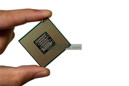
Rogers TMM® 3 Substrate Manufacturer
What is the Rogers TMM® 3 Substrate Design Guidelines?
Design guidelines for Rogers TMM® 3 substrate are crucial for ensuring optimal performance and reliability in RF and microwave circuit designs. Here are some key aspects typically covered in design guidelines for Rogers TMM® 3 substrate:
- Material Properties: Understand the electrical properties such as dielectric constant (εr), loss tangent (tan δ), and thermal conductivity. These properties affect signal propagation, power handling, and thermal management in the circuit.
- Layer Stackup: Define the optimal layer configuration and thicknesses to achieve desired impedance, considering factors like signal frequency, impedance requirements, and manufacturing feasibility.
- Transmission Line Design: Design transmission lines (microstrip, stripline, coplanar waveguide, etc.) based on the substrate’s characteristics to minimize losses, impedance mismatches, and electromagnetic interference (EMI).
- Component Placement: Place components strategically to minimize signal distortion and interference. Consideration of spacing, orientation, and grounding techniques is essential to maintain signal integrity.
- Via Design: Optimize via placements and sizes for signal transitions between layers while maintaining impedance control and minimizing signal reflections and losses.
- Thermal Management: Manage heat dissipation effectively to prevent overheating of components and substrate. Consider the substrate’s thermal conductivity and design cooling solutions accordingly.
- Manufacturing Tolerances: Account for manufacturing tolerances and capabilities when specifying dimensions, trace widths, and spacing to ensure consistent performance across production batches.
- Environmental Considerations: Evaluate the substrate’s performance under different environmental conditions (temperature, humidity, etc.) to ensure reliability over the product’s lifecycle.
- Testing and Validation: Develop testing procedures to verify circuit performance against design specifications, including impedance matching, insertion loss, and return loss measurements.
- Compliance and Standards: Ensure compliance with industry standards and regulations (e.g., IPC standards) for PCB design and fabrication to meet quality and reliability requirements.
By following these guidelines, designers can leverage the unique electrical and mechanical properties of Rogers TMM® 3 substrate to optimize RF and microwave circuits for superior performance, reliability, and longevity in demanding applications.
The advantages of Rogers TMM® 3 Substrate
Rogers TMM® 3 substrate offers several advantages that make it highly suitable for RF (Radio Frequency) and microwave applications:
- Low Dielectric Constant (εr): TMM® 3 substrate has a low dielectric constant, which helps in minimizing signal loss and maintaining signal integrity, especially at higher frequencies. This property is crucial for achieving efficient signal transmission in RF circuits.
- Low Loss Tangent (tan δ): The low loss tangent of TMM® 3 substrate ensures minimal energy dissipation as signals propagate through the material. This characteristic is essential for reducing insertion loss and improving overall circuit efficiency.
- Excellent Electrical Performance: TMM® 3 substrate exhibits stable electrical properties across a wide range of frequencies and temperatures. It provides predictable impedance characteristics, enabling precise control over signal impedance matching in RF designs.
- Mechanical Stability: The substrate’s robust mechanical properties ensure dimensional stability and reliability during manufacturing and throughout its operational life. This stability is critical for maintaining consistent performance and preventing mechanical deformation under varying environmental conditions.
- Thermal Management: TMM® 3 substrate has good thermal conductivity properties, aiding in effective heat dissipation from components mounted on the PCB. This capability helps in managing temperature rise within the circuit, thereby enhancing overall reliability and longevity.
- Compatibility with High-Frequency Designs: Designed specifically for high-frequency applications, TMM® 3 substrate supports the development of high-performance RF circuits, antennas, radar systems, and other wireless communication devices where efficient signal transmission is essential.
- Ease of Manufacturing: The substrate’s design and manufacturing processes are optimized for reliability and consistency, allowing for precise fabrication of complex RF and microwave circuits. This ensures high manufacturing yields and cost-effectiveness in production.
- Industry Standard Compliance: Rogers TMM® 3 substrate meets stringent industry standards and specifications, ensuring compatibility with established RF design practices and regulatory requirements.
Overall, Rogers TMM® 3 substrate’s combination of low dielectric constant, low loss tangent, excellent electrical performance, mechanical stability, and thermal management capabilities makes it a preferred choice for engineers designing high-frequency and high-performance RF/microwave circuits that require reliability, efficiency, and consistency.
What is the Rogers TMM® 3 Substrate Fabrication Process?
The fabrication process for Rogers TMM® 3 substrate involves several key steps to ensure the material meets stringent requirements for RF (Radio Frequency) and microwave applications. Here’s an overview of the typical fabrication process:
- Material Selection and Preparation:Rogers TMM® 3 substrate is typically composed of layers of woven fiberglass reinforcement impregnated with thermoset resin systems. The materials are selected for their high dielectric constant uniformity, low loss tangent, and mechanical stability.
- Layer Preparation:The fiberglass layers are treated and prepared to ensure uniform resin distribution and adherence. This step is crucial for achieving consistent electrical and mechanical properties across the substrate.
- Lamination:The prepared layers are stacked according to the desired layer configuration (stackup) based on the circuit design requirements. Between each layer, the resin is cured under controlled temperature and pressure to form a solid laminate.
- Curing:The lamination stack undergoes a curing process where the resin is hardened through a combination of heat and pressure. This step ensures the substrate achieves its final mechanical strength and dimensional stability.
- Drilling and Routing:After curing, the substrate undergoes precision drilling and routing processes to create holes (vias) and define the outlines of the PCB layout. These processes require high precision to maintain the integrity of the substrate and ensure accurate electrical performance.
- Surface Preparation:The substrate surfaces are prepared for subsequent processes such as metallization and solder mask application. Surface cleaning and treatment are critical to ensure proper adhesion and functionality of the circuit components.
- Metallization:Conductive metal layers (typically copper) are deposited onto the substrate surfaces through processes such as electroless plating or sputtering. These metal layers form the circuit traces and interconnects that carry electrical signals throughout the PCB.
- Etching and Plating:Excess copper is removed from the substrate surfaces through etching processes, leaving behind the desired circuit patterns. Plating processes may follow to enhance conductor thickness and ensure uniformity across the PCB.
- Solder Mask Application:A solder mask layer is applied over the substrate to insulate the conductive traces, protect against environmental factors, and define soldering areas. This layer also aids in preventing solder bridges and ensuring reliable solder joints.
- Final Inspection and Testing:The fabricated PCB undergoes rigorous inspection and testing to verify dimensional accuracy, electrical continuity, and adherence to design specifications. Testing may include electrical performance tests, impedance measurements, and visual inspections.
- Packaging and Shipping:Once verified, the Rogers TMM® 3 substrate PCBs are packaged according to customer requirements and shipped for assembly into electronic devices or systems.
Throughout the fabrication process, stringent quality control measures are implemented to ensure that Rogers TMM® 3 substrates meet the high standards required for reliable operation in RF and microwave applications. This includes adherence to industry standards and specifications to guarantee consistent performance and durability.
The application of ceramic Rogers TMM® 3 Substrate
Rogers TMM® 3 substrate, being a high-performance material with excellent electrical and mechanical properties, finds application in various critical RF (Radio Frequency) and microwave circuits where reliability, efficiency, and signal integrity are paramount. Some key applications of Rogers TMM® 3 substrate include:
- RF/Microwave Circuits: TMM® 3 substrate is extensively used in the fabrication of RF and microwave circuits such as amplifiers, filters, oscillators, and mixers. Its low dielectric constant and low loss tangent ensure minimal signal loss and high signal fidelity, making it ideal for high-frequency applications.
- Antennas: Due to its stable electrical properties and mechanical strength, Rogers TMM® 3 substrate is employed in the design of antennas for wireless communication systems, radar systems, satellite communications, and other applications requiring efficient electromagnetic wave propagation.
- High-Speed Digital Circuits: In high-speed digital circuits where signal integrity is critical, TMM® 3 substrate helps in minimizing signal distortion and ensuring reliable performance. It supports the development of PCBs (Printed Circuit Boards) for data communication, computing, and networking equipment.
- Aerospace and Defense: The substrate’s robust mechanical stability and thermal management capabilities make it suitable for aerospace and defense applications. It is used in radar systems, avionics, communication systems, and electronic warfare equipment where durability and performance under harsh environmental conditions are essential.
- Automotive Radar Systems: With the increasing integration of radar systems in automotive applications (e.g., collision avoidance systems, adaptive cruise control), Rogers TMM® 3 substrate plays a crucial role in ensuring reliable and accurate radar signal processing and transmission.
- Medical Devices: TMM® 3 substrate is also employed in medical devices and equipment where high-frequency signals are used, such as MRI machines, diagnostic imaging systems, and wireless medical telemetry systems.
- Telecommunications: In telecommunications infrastructure, Rogers TMM® 3 substrate supports the development of base station equipment, repeaters, and other devices requiring high-frequency signal processing and transmission.
- Test and Measurement Equipment: Due to its predictable electrical properties and high-performance characteristics, TMM® 3 substrate is utilized in test and measurement equipment for RF and microwave signal testing, calibration, and analysis.
Overall, Rogers TMM® 3 substrate’s versatility and reliability make it a preferred choice in industries and applications demanding high-frequency performance, durability, and consistent electrical properties. Its use enhances the efficiency and reliability of electronic systems operating in demanding environments.
FAQs about Rogers TMM® 3 Substrate
What are the key properties of Rogers TMM® 3 substrate?
Rogers TMM® 3 substrate is known for its low dielectric constant (εr) and low loss tangent (tan δ), which ensure minimal signal loss and high signal fidelity at high frequencies. It also offers excellent mechanical stability and thermal management capabilities.
What applications is Rogers TMM® 3 substrate suitable for?
Rogers TMM® 3 substrate is suitable for RF and microwave circuits, antennas, high-speed digital circuits, aerospace and defense systems, automotive radar, medical devices, telecommunications equipment, and test and measurement instruments.
How does Rogers TMM® 3 substrate compare to other materials like FR4?
Compared to standard FR4 substrates, Rogers TMM® 3 offers superior electrical performance, particularly at high frequencies. It has lower loss characteristics and better dimensional stability, making it ideal for applications requiring high reliability and performance.
What are the advantages of using Rogers TMM® 3 substrate in RF designs?
The substrate’s low dielectric constant and low loss tangent enable efficient signal transmission with minimal loss, ensuring high performance and reliability in RF applications. Its mechanical robustness and thermal conductivity also contribute to overall system reliability.
Is Rogers TMM® 3 substrate compatible with standard PCB manufacturing processes?
Yes, Rogers TMM® 3 substrate can be processed using standard PCB manufacturing techniques such as drilling, etching, and solder mask application. However, it requires careful handling due to its unique electrical properties and material composition.
What are some design considerations when using Rogers TMM® 3 substrate?
Designers should consider impedance matching, thermal management, component placement, and manufacturing tolerances to optimize the performance of circuits using Rogers TMM® 3 substrate. Compliance with industry standards and specifications is also important.
Where can I purchase Rogers TMM® 3 substrate?
Rogers Corporation and its authorized distributors typically supply Rogers TMM® 3 substrate. It’s recommended to contact them directly for purchasing inquiries, technical support, and product availability.
 Your Website Name


