Rogers TMM® 10 Substrate Manufacturer
Rogers TMM® 10 Substrate Manufacturer,Rogers TMM® 10 Substrate is an advanced microwave material engineered for high-frequency applications. Known for its exceptional performance in RF and microwave circuits, it features a low dielectric constant and low loss tangent, ensuring minimal signal loss and precise electrical characteristics. Rogers TMM® 10 Substrate supports intricate circuit designs and high-speed signal transmission, critical for telecommunications, radar systems, and aerospace electronics. It provides reliable performance in demanding environments where signal integrity and thermal management are paramount. Rogers TMM® 10 Substrate is widely used in the industry for its robustness and ability to meet stringent requirements for high-frequency electronic applications.
What is Rogers TMM® 10 Substrate?
Rogers TMM® 10 (Thermoset Microwave Materials) substrate is a high-performance material designed primarily for microwave and RF applications. It offers excellent electrical properties suitable for high-frequency circuit designs, including low loss tangent (typically around 0.0023) and stable dielectric constant (εr) across a wide frequency range. This stability is crucial for maintaining signal integrity and minimizing losses in microwave and millimeter-wave circuits.
TMM® 10 substrates are known for their reliability in demanding environments, making them ideal for applications such as radar systems, satellite communications, and high-speed wireless networks. They are engineered to withstand varying temperatures and environmental conditions while maintaining consistent electrical performance.
In terms of fabrication, TMM® 10 substrates can be processed using standard PCB manufacturing techniques, including drilling, plating, and etching. This makes them relatively straightforward to integrate into existing production processes, enhancing their appeal for industrial and aerospace applications where reliability and performance are critical factors.
Overall, Rogers TMM® 10 substrates represent a significant choice for engineers and designers seeking high-frequency circuit solutions that prioritize low loss, stable performance, and durability in challenging operational conditions.
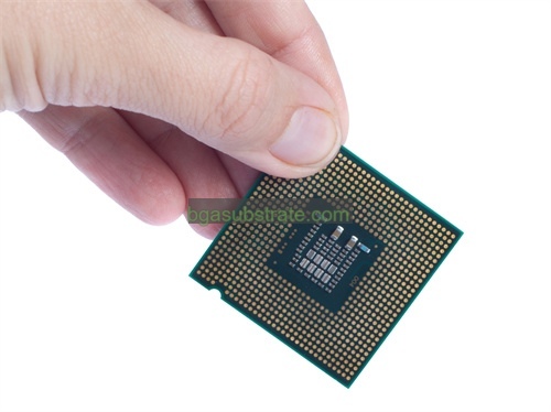
Rogers TMM® 10 Substrate Manufacturer
What is the Rogers TMM® 10 Substrate Design Guidelines?
Design guidelines for Rogers TMM® 10 substrates are crucial for ensuring optimal performance in high-frequency microwave and RF applications. Here are some key design considerations:
- Material Properties: Understand the electrical properties of TMM® 10, such as its dielectric constant (εr) and loss tangent (tan δ). These properties are critical for calculating characteristic impedance, propagation delay, and signal attenuation in your circuits.
- Layer Stackup: Design the layer stackup carefully to achieve the desired impedance and signal integrity. TMM® 10 substrates typically require controlled impedance traces to minimize signal loss and reflections. Use impedance calculation tools to determine trace widths and separations.
- Transmission Line Design: Implement transmission lines (microstrip or stripline) with appropriate dimensions and separation from ground planes to maintain consistent impedance. Ensure the substrate thickness and dielectric constant are accurately accounted for in your calculations.
- Via Design: Vias play a crucial role in connecting different layers of the PCB. Ensure via sizes and placement minimize impedance discontinuities and maintain signal integrity. Consider via stubs and their effects on high-frequency performance.
- Component Placement: Place RF components strategically to minimize signal path lengths and impedance mismatches. Keep sensitive components away from high-power areas or sources of electromagnetic interference (EMI).
- Grounding: Proper grounding is essential for RF circuits to minimize noise and ensure stable operation. Use a solid ground plane and avoid splits or discontinuities that could introduce impedance variations.
- Thermal Management: Consider heat dissipation requirements, especially in power RF applications. Ensure adequate thermal vias and thermal relief for components connected to the ground plane.
- Manufacturing Tolerances: Understand the manufacturing capabilities and tolerances of your PCB fabricator when designing with TMM® 10 substrates. Communicate specific requirements for material thickness, copper thickness, and registration accuracy.
- Simulation and Testing: Perform electromagnetic simulation (e.g., using tools like HFSS, CST Microwave Studio) to validate your design before fabrication. Conduct signal integrity and impedance testing on prototypes to verify performance against design specifications.
By adhering to these design guidelines, engineers can leverage the high-frequency capabilities of Rogers TMM® 10 substrates effectively, ensuring reliable performance and optimal signal integrity in microwave and RF circuits.
The advantages of Rogers TMM® 10 Substrate
Rogers TMM® 10 substrate offers several advantages that make it highly suitable for high-frequency microwave and RF applications:
- Low Dielectric Loss: TMM® 10 substrates exhibit a low loss tangent (typically around 0.0023), which minimizes signal attenuation and ensures efficient signal transmission at high frequencies. This characteristic is crucial for maintaining signal integrity in RF circuits.
- Stable Electrical Properties: The substrate maintains a stable dielectric constant (εr) across a wide frequency range. This stability is essential for predictable performance of microwave circuits, enabling accurate design and consistent operation.
- High Mechanical Strength: TMM® 10 substrates are engineered to withstand mechanical stresses and environmental factors, making them reliable for applications where durability is critical, such as in aerospace and defense systems.
- Ease of Processing: These substrates are compatible with standard PCB fabrication processes, including drilling, plating, and etching. This compatibility simplifies integration into existing manufacturing workflows, reducing production time and costs.
- Broad Frequency Range:Suitable for applications spanning microwave and millimeter-wave frequencies, TMM® 10 substrates support the development of high-frequency circuits used in radar systems, satellite communications, and wireless networks.
- Thermal Stability: TMM® 10 substrates exhibit good thermal management properties, helping to dissipate heat efficiently in high-power RF applications. This characteristic contributes to the substrate’s reliability and longevity under varying operational conditions.
- Proven Reliability: Rogers TMM® 10 substrates have a track record of reliability in demanding environments, backed by extensive testing and validation. This reliability makes them a preferred choice for mission-critical applications where performance consistency is paramount.
- Design Flexibility: Engineers have the flexibility to design complex RF circuits with precise impedance control and signal integrity, thanks to the substrate’s consistent electrical properties and compatibility with advanced PCB design techniques.
In summary, Rogers TMM® 10 substrate combines low loss, stable electrical characteristics, mechanical robustness, and ease of processing, making it an ideal choice for high-frequency RF and microwave applications that require reliable performance and efficiency.
What is the Rogers TMM® 10 Substrate Fabrication Process?
The fabrication process for Rogers TMM® 10 substrates involves several key steps to ensure the material’s properties are maintained for high-frequency RF and microwave applications:
- Material Selection: Rogers TMM® 10 substrate material is chosen based on its specific dielectric constant (εr) and low loss tangent (tan δ), which are critical for high-frequency performance. The material is typically supplied in sheets or panels.
- Preparation and Cleaning: The substrate sheets undergo thorough cleaning to remove any contaminants that could affect adhesion and quality during subsequent processing steps. This cleaning ensures a clean surface for proper lamination and etching.
- Layer Stackup Design: Engineers design the layer stackup according to the specific requirements of the RF circuit. This includes determining the number of layers, copper thicknesses, and the arrangement of signal and ground planes to achieve the desired impedance and signal integrity.
- Lamination: The TMM® 10 substrate sheets are laminated together with copper foil using heat and pressure. This process creates a multilayered structure where the copper serves as conductive pathways for electrical signals, while the substrate material provides insulation and support.
- Drilling: Precision drilling is conducted to create holes for vias and component mounting pads. The drill holes are carefully aligned to ensure accuracy and consistency across the substrate panel.
- Copper Plating: After drilling, the substrate undergoes copper plating to form conductive vias that connect different layers of the PCB. This step is crucial for maintaining electrical continuity and achieving controlled impedance throughout the circuit.
- Etching: A photolithographic process is used to selectively remove excess copper from the substrate surface, leaving behind the desired circuit traces and pads. Chemical etchants dissolve the unprotected copper, defining the circuit pattern according to the design specifications.
- Surface Finish: The finished PCB surface is coated with a surface finish to protect the copper traces from oxidation and to facilitate soldering during component assembly. Common surface finishes include HASL (Hot Air Solder Leveling), ENIG (Electroless Nickel Immersion Gold), and OSP (Organic Solderability Preservative).
- Testing and Inspection: Quality control procedures involve electrical testing to verify impedance, continuity, and insulation resistance. Visual inspection and automated optical inspection (AOI) ensure the PCB meets design tolerances and quality standards.
- Final Processing: After testing and inspection, the PCB panels are routed or scored to separate individual boards. Any remaining fabrication residues are cleaned off, and the boards may undergo final testing to ensure they meet performance specifications before being packaged and shipped.
Throughout the fabrication process, strict adherence to design guidelines and quality control measures ensures that Rogers TMM® 10 substrates maintain their high-frequency performance characteristics, making them suitable for demanding RF and microwave applications.
The application of ceramic Rogers TMM® 10 Substrate
Rogers TMM® 10 substrates, being high-performance materials tailored for RF and microwave applications, find extensive use in various demanding electronic systems where high-frequency performance and reliability are critical. Some key applications include:
- Wireless Communications: TMM® 10 substrates are commonly used in base station antennas, RF amplifiers, and other components of wireless communication systems. Their low loss tangent and stable dielectric properties help maintain signal integrity and efficiency in transmitting and receiving signals across different frequencies.
- Radar Systems: In radar systems, where precise detection and ranging capabilities are crucial, TMM® 10 substrates support the development of radar antennas, transceivers, and signal processing modules. Their high mechanical strength and thermal stability ensure reliable operation in aerospace, defense, and automotive radar applications.
- Satellite Communications: TMM® 10 substrates are employed in satellite transponders, receivers, and microwave components due to their ability to handle high frequencies and maintain consistent electrical performance in space environments. They contribute to the reliability and longevity of satellite communication systems.
- Test and Measurement Equipment: Precision instruments such as spectrum analyzers, network analyzers, and signal generators benefit from TMM® 10 substrates’ low loss properties, which enable accurate measurement and analysis of RF signals without significant attenuation.
- Medical Devices: In medical electronics, TMM® 10 substrates are utilized in devices such as MRI coils, ultrasound equipment, and RF ablation systems. Their high-frequency capabilities support the transmission and processing of medical data and signals with minimal interference or loss.
- Industrial Applications: TMM® 10 substrates are integral to industrial RF applications, including industrial automation, process control systems, and RFID (Radio Frequency Identification) technology. Their robustness and performance under harsh industrial conditions make them suitable for reliable data transmission and communication.
- Consumer Electronics: Increasingly, TMM® 10 substrates are being used in consumer electronics like high-frequency wireless routers, smart home devices, and wearable technology. These applications benefit from the substrate’s ability to maintain signal strength and reliability in compact, high-performance devices.
Overall, Rogers TMM® 10 substrates play a vital role in enabling advanced RF and microwave technologies across diverse industries, supporting innovations in communication, sensing, and high-speed data processing systems. Their unique combination of low loss, stability, and durability makes them an ideal choice for applications where performance and reliability are paramount.
FAQs about Rogers TMM® 10 Substrate
What is Rogers TMM® 10 substrate?
Rogers TMM® 10 is a high-performance ceramic-filled PTFE (Polytetrafluoroethylene) material designed for RF and microwave applications. It offers low dielectric loss and stable electrical properties across a wide frequency range.
What are the key advantages of Rogers TMM® 10 substrate?
TMM® 10 substrate provides low loss tangent, stable dielectric constant, high mechanical strength, and thermal stability. These properties make it suitable for high-frequency circuits requiring reliable performance.
What applications are suitable for Rogers TMM® 10 substrate?
It is used in wireless communications systems, radar systems, satellite communications, medical devices, industrial RF applications, and consumer electronics. It supports applications requiring high-frequency signal integrity and durability.
How does Rogers TMM® 10 substrate compare to other materials like FR4?
Compared to standard materials like FR4 (a fiberglass epoxy laminate), TMM® 10 substrate offers superior high-frequency performance with lower loss and more stable electrical properties. It is ideal for applications where RF performance is critical.
What are the typical fabrication processes involved in using Rogers TMM® 10 substrate?
Fabrication includes material preparation, layer stackup design, lamination with copper foil, drilling, copper plating, etching, surface finishing, and testing. These processes ensure the substrate meets design specifications for impedance control and signal integrity.
Can Rogers TMM® 10 substrate be used in harsh environments?
Yes, TMM® 10 substrate is designed to withstand harsh environmental conditions, including temperature variations and mechanical stress. It is suitable for applications in aerospace, defense, and industrial sectors where reliability is crucial.
How do I ensure optimal performance when designing with Rogers TMM® 10 substrate?
Follow design guidelines for impedance control, transmission line design, via placement, and thermal management. Use simulation tools to validate designs and conduct thorough testing to verify performance before deployment.
 Your Website Name


